CBSE Class 10 Science Notes of Chapter 12 Electricity, Video Explanation, and Question Answers
Electricity Class 10 – Here is a Complete Explanation and Notes of Class 10 Science Chapter 12 ‘Electricity’.
Topics covered in the lesson are Friction, Electric current, Electric charge, Electric circuit, Coulomb’s law, Ohm’s law, Types of substances depending upon their ability to conduct current, Joule’s heating effect of current, Types of electricity, Power, Electrostatic Potential, Electric fuse, Potential difference.
Given here is the complete explanation of the chapter, along with all the important questions and NCERT solutions to book questions have also been provided for the ease of students
CBSE Class 10 Science Chapter 12
Electricity
- See Video Explanation of Electricity
- Friction
- Electric current
- Electric charge
- Electric circuit
- Coulomb’s law
- Ohm’s law
- Types of substances depending upon their ability to conduct current
- Joule’s heating effect of current
- Types of electricity
- Power
- Electrostatic Potential
- Electric fuse
- Potential difference
- NCERT Book solutions
Introduction
The concept of electricity came into notice due to friction. It actually proves that charges can be produced and they can also be made to flow and flowing of charges gives rise to electricity. So let us first learn about friction.
Electricity Class 10 Video Explanation
Electricity Related Links
| Electricity MCQs | |
| Electricity Video Explanation | Electricity MCQs Video |
| Electricity Important Question Answers | Electricity Important Question Answers Video |
Friction
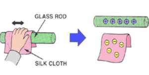
It comes into notice when two bodies are rubbed with each other.
For example: Rubbing of a glass rod with silk. When a glass rod is rubbed with silk, electrons move from glass rod to silk therefore, the glass rod acquires a positive charge as it becomes deficient of electrons and silk will acquire negative charge as the amount of negative charge in it increases.
So, due to this concept of friction, the concept of charges came in to notice. And further, coulomb was the one who gave more information about the charges.
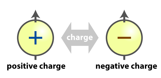
Electric charge
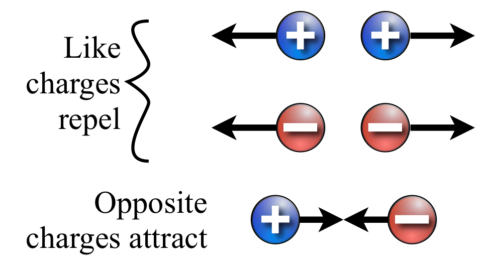
So it was concluded that we have two types of charges:
- Positive charge
- Negative charge
The symbol used for it is (q) and unit that is used to measure it is Coulomb which is denoted by C (unit).

Different experiments proved that “same charges repel each other and opposite charges attract each other.”
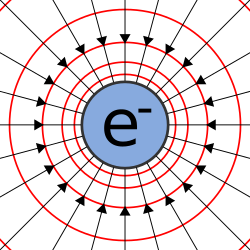
And also, when the electric charges are kept, they create a small area around itself where its effect can be felt called as the electric field.
The electric charge is equal to the number of electrons in it and the magnitude of charge on the electron i.e.
q = ne
where n = number of electrons and
e = charge of electron
= 1.6 x 10⁻¹⁹ C
Q. Calculate number of electrons in 1C of charge
Ans) Q= ne
Q= i.e.
So, 1 = n x 1.6 x 10 -19
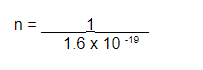
Therefore, we can define 1c as :
1c is that charge which contains 6.25 x 10¹⁸ number of electrons in it.
Top
Related – Tips to score 95% in Class 10 Science Paper
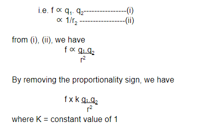
Coulomb’s law
There is always some force between two charges which is directly proportional to the product of magnitude of their charges & inversely proportional to the square of the distance between them.
Types of substances depending upon their ability to conduct current
We have different kinds of substances depending upon their power to conduct electricity. They are classified as:
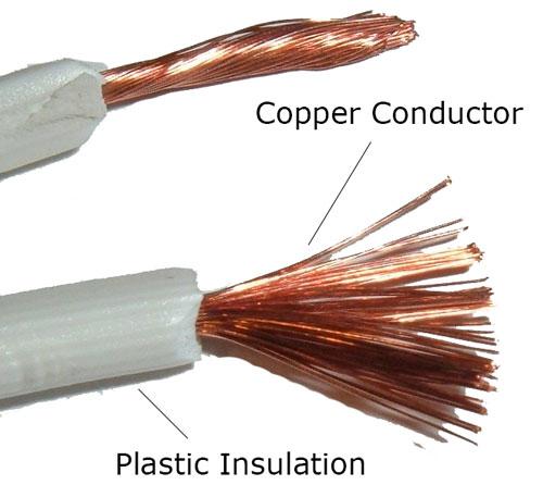
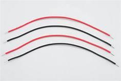
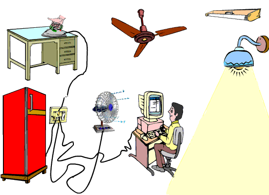
Conductors –They are those which allow current to pass through them. They have free mobile electrons.
For example Cu, Al, etc. Like in the given figure, the wire conducts electricity but the plastic insulation is an insulator.
Insulators-They are those which do not allow current to pass through them as they do not have free mobile electrons.
For example glass etc. Those substances which give free electrons are good conductors and those which don’t have free electrons are poor conductors.
Types of electricity
- Static electricity
- Current electricity
Static Electricity: Static electricity is a type of electricity when electric charges develop but do not flow.
For example charges developed by glass rod are rubbed with silk.
Current Electricity:Current electricity is a type of electricity when the electronic charges that develop are also in motion.
For example electricity used in our homes.
Electrostatic potential
It is the work done in moving the positive charge from infinity to a certain point in an electric field of other charge.
For example – A unit of positive charge is at a point at infinity and we try to bring it to point b that is in the electric field of some other charge, let’s say charge q2. So the work that we need to do in doing so is called electrostatic potential.
Potential difference
When we need to move the charge between two specified points, then the work done in doing so is called the potential difference. So it is defined as the work done in moving a charge from one point to another point.
i.e. V= W (from one point to another)
q
The unit that is used to measure it is volt and we can define 1 volt as :1v = 1 joule
1 coulomb
So it is defined as:
The potential difference is said to be 1 volt when 1J of work is done in moving IC of charge from one point to another. The instrument that is used to measure its magnitude is called Voltmeter.
There is an important feature that how we connect it. It is connected in parallel because it has a high resistance and also in parallel the potential difference remains constant.
Electric current
As we have understood that charges do move, so here comes another physical quantity that is the rate of flow of electric charge through a conductor.
I = Q
T
The Unit that is used to measure it is ampere.
1A = 1C
1 sec
We can define 1 ampere current as 1A, when 1Coulomb of charge flows through wire in 1second.
The ammeter is an instrument used to measure the current. Now the connection of ammeter in circuit is that it is connected in series. It has low resistance and in series, the current remains constant.
Q) How can we get continuous flow of current in a circuit?
Ans) We can get continuous flow of current in a circuit by maintaining a potential difference between the 2 ends of a conductor. We can do that by connecting it to a battery or cell because there are two terminals that are always at different potential levels.
Types of current:
| Conventional | Electric |
| Flow of protons | Flow of electrons |
| More from +ve terminal to –ve terminal in outer circuit. | Move from – ve terminal to +ve terminal. |
| practically not important | Practically important |
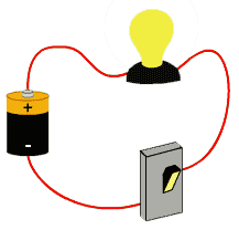
Electric circuits
A continuous conducting path between the terminals of a source of electric energy and other electrical components along which the electric current flows is called an electric circuit.
Types of electric circuits:
- Closed electric circuit
- Open circuit
Open electric circuit : It is the circuit in which electric contact is broken at some point such that no current flows through the components of the circuit.
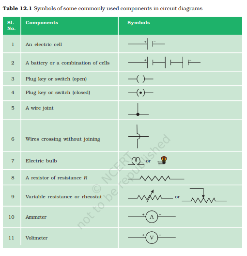
Closed electric circuit: The circuit in which all the components of a circuit are joined to one another such that a continuous current flows through them is a closed electric circuit. Some electronic devices with symbols used are:
Rheostat – It is defined as the variable resistance. It is connected to change the current in the circuit without changing the voltage source like cell etc.
Galvanometer– It is a device used to measure a very small amount of current as it has very low resistance.
Ohm’s law
It is the generalization made by ohm on the basis of the experiments he conducted. According to it, at a constant temperature, the current flowing through the circuit is directly proportional to the potential difference applied across the ends of the conductor.
i.e. V x I
Removing proportionately sign, we have
V= I
Constant Resistance.
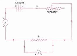
Verification of ohm’s law: It can be verified as in this we connect the circuit as shown in the figure.
In this, a rheostat is introduced whose resistance can be increased or decreased. In the first case, the resistance of rheostat is kept minimum and accordingly when we switch on the current, the ammeter records the magnitude of the current and voltmeter records the potential difference- we take their values as I1 and V1. Now the slider of rheostat is moved such that its resistance increases slightly and then again ammeter and voltmeter take the reading as I2 and V2. Likewise, we take 5 consecutive readings and after comparing them we concluded that V1/I1=V2/I2=V3/I3 and so on.
Resistance– It is the obstruction to flow of charge.
Formula: R=V/I
Unit: ohm
We can define 1ohm as – resistance is said to be 1 ohm when 1volt of potential difference is applied which allows 1 ampere current to flow through it.
Factors on which resistance depends :
- Dependence of resistance on length of wire: Resistance is directly proportional to the length of the wire. More is the length of wire, more is the number of collisions and more is the resistance.
Resistance on area of wire: Resistance is inversely proportional to the area of the wire. More is the area, less is the resistance as number of collisions is less as they can pass easily.
Resistance on nature of wire: Depending upon the material used for making wires we have:
Conductors: have almost nil resistance
Semiconductors: have resistance
Insulators: have high resistance
Resistance on temperature: Resistance is directly proportional to temperature for pure metals but for alloys it decreases. With increase in the temperature, number of collisions are more, therefore, resistance is more. Combining all factors we get :
R= rho L/A
Specific resistance or resistivity: In the above formula of resistance, if we consider it for wire of length 1m and area 1m2 then resistivity is defined as the measure of resistance of wire 1m length and 1 meter square area .
formula : R= rho L/A
unit is ohm –metre
Resistance can be introduced in a circuit in 2 ways:
Resistance in series: In series, the resistances are attached as shown
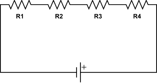
In series, the current remains constant and potential difference changes.
Resistance in parallel: They are connected as shown in figure :
In parallel, Potential Difference remains constant and the current changes.
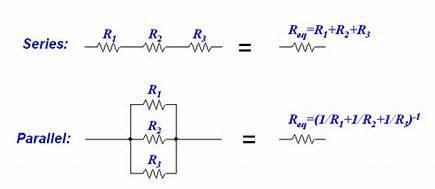
Derive expression to calculate equivalent resistance when different resistances are connected in series :
Let’s say same current ‘I’ passes through resistances R1 and R2 and potential difference is V1 and V2.
Then we can write :
V=V1 +V2
IR=IR1 +IR2
Or we can write
R=R1+R2
Expression to calculate equivalent resistance when different resistances are connected in parallel. Let’s say same current I1 AND I2 passes through resistances R1 and R2 and potential difference is V.
Then we can write :
I=I1+I2
V/R=V/R1 +V/R2
V(1/R=1/R1+1/R2)V
Or we can write
1/R=1/R1+1/R2 —–
Joules heating effect of current
When current flows, the electrons move and when they move, they collide with each other. When they collide, heat is produced. Heat produced depends upon the square of current, resistance and temperature.
i.e.,: H=I2RT
Also called as joules heating effect.
You know that nichrome wire is used in heating devices and the reason being
because
- It has high resistance
- It does not burn even at high temperature
- It has high coefficient of linear expansion
Power
We come across ‘power’ that is mentioned on all electrical appliances. So, if we define, it is the rate of doing work.
Formula : P=w/t
Unit : joule/sec
Bigger units : kilowatt=1000watt
megawatt=1000000 watt
gigawatt=1000000000watt
horsepower =746 watts
Further derived formulas of power :
P=v.i
P=v2/r
P=i2/r
Electric fuse
It is a safety device that protects us from fire. It is shown in figure. It has two terminals T1 and T2 to which fuse wire is attached. The property of fuse wire is that it has very very low melting point. It is made up of an alloy consisting of lead and tin.
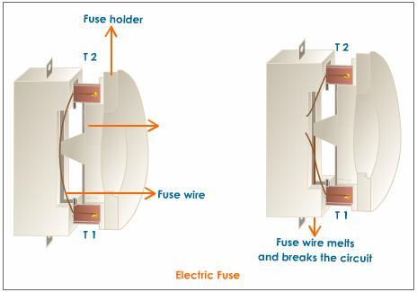
It works under two conditions:
- Overloading: When many appliances are running together at the same time, they draw a large amount of current which produces a lot of heat that can even lead to fire.
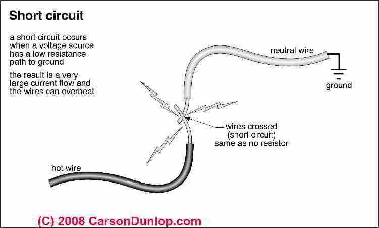
- Short circuiting: When live wire and neutral wire touch each other, the current exceeds the normal value and it can also cause fire.
- In both the conditions, when current exceeds the normal value, excess heat is produced which melts the fuse wire and hence, fire is caused.
Top
Important Videos Links
NCERT Solutions Class 10 Electricity
1. A piece of wire of resistance R is cut into five equal parts. These parts are then connected in parallel. If the equivalent resistance of this combination is ‘R′, then the ratio ‘R/R′ is –
(a) 1/25
(b) 1/5
(c) 5
(d) 25
Ans. (d) 25
2. Which of the following terms does not represent electrical power in a circuit?
(a) I 2R
(b) IR2
(c) VI
(d) V 2/R
Ans. (b) IR2
3. An electric bulb is rated 220 V and 100 W. When it is operated on 110 V, the power consumed will be –
(a) 100 W
(b) 75 W
(c) 50 W
(d) 25 W
Ans. (d) 25W
4. Two conducting wires of the same material and of equal lengths and equal diameters are first connected in series and then parallel in a circuit across the same potential difference. The ratio of heat produced in series and parallel combinations would be –
(a) 1:2
(b) 2:1
(c) 1:4
(d) 4:1
Ans. (c) 1:4
5. How is a voltmeter connected in the circuit to measure the potential difference between two points?
Ans. To measure the potential difference between two points, a voltmeter should be connected in parallel across these points.
Concept Insight:- Voltmeter is always connected in parallel to the element of any electrical circuit across which potential difference is to be measured.
6. A copper wire has diameter 0.5 mm and resistivity of 1.6 × 10⁻⁸ Ω m. What will be the length of this wire to make its resistance 10 Ω? How much does the resistance change if the diameter is doubled?
Ans. Resistance (R) of the copper wire of length (l) and cross-section (A) is given by the expression,

where,

Resistivity of copper,

Area of cross-section of the wire,
Diameter = 0.5 mm = 0.0005 m
Resistance, R = 10 Ω
We know that,

Therefore, the length of the wire is 122.72 m.
So, if the diameter of the wire is doubled, the new diameter = 2 × 0.0005 = 0.001 m.
Let the new resistance be R’.

Therefore, the new resistance is 2.5 Ω.
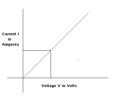
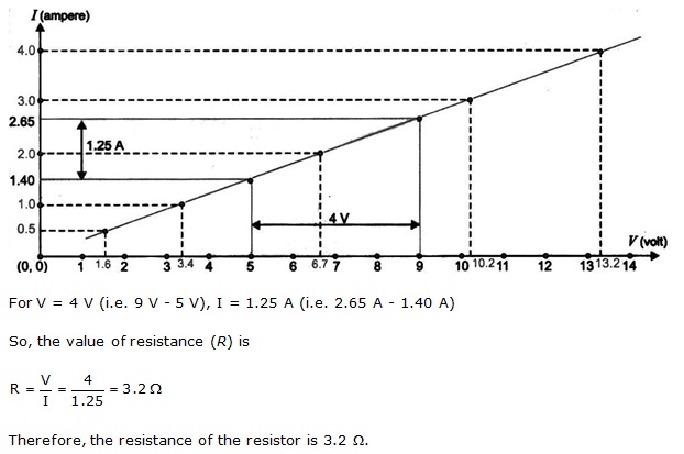
7. The values of current I flowing in a given resistor for the corresponding values of potential difference V across the resistor are given below – I (amperes) 0.5 1.0 2.0 3.0 4.0 V (volts) 1.6 3.4 6.7 10.2 13.2 Plot a graph between V and I and calculate the resistance of that resistor.
Ans. The VI graph is shown below. The voltage is plotted on x -axis and current is plotted on y -axis.
8. When a 12 V battery is connected across an unknown resistor, there is a current of 2.5 mA in the circuit. Find the value of the resistance of the resistor.
Ans. Resistance (R) of a resistor is given by Ohm’s law as,
V = IR

R =
where,
Potential difference, V = 12 V
Current in the circuit, I = 2.5 mA = 2.5 x 10⁻³ A
9. A battery of 9 V is connected in series with resistors of 0.2 Ω, 0.3 Ω, 0.4 Ω , 0.5 Ω and 12 Ω, respectively. How much current would flow through the 12 Ω resistor?
Ans. There is no current division occurring in a series circuit. Current flow through all the components is the same, given by Ohm’s law as
V = IR
where,
V = Potential difference
I = Current through the circuit
R = Resistance of the circuit
Let R be the equivalent resistance of resistances 0.2 ohm, 0.3 ohm, 0.4 ohm, 0.5 ohm and 12 ohm.
These are connected in series. Hence, the sum of the resistances will give the value of R.
R = 0.2 + 0.3 + 0.4 + 0.5 + 12 = 13.4 ohm
Potential difference, V = 9 V
Therefore, the current that would flow through the circuit and hence 12 ohm resistor is
I = V/R = 9/13.4 = 0.67 A
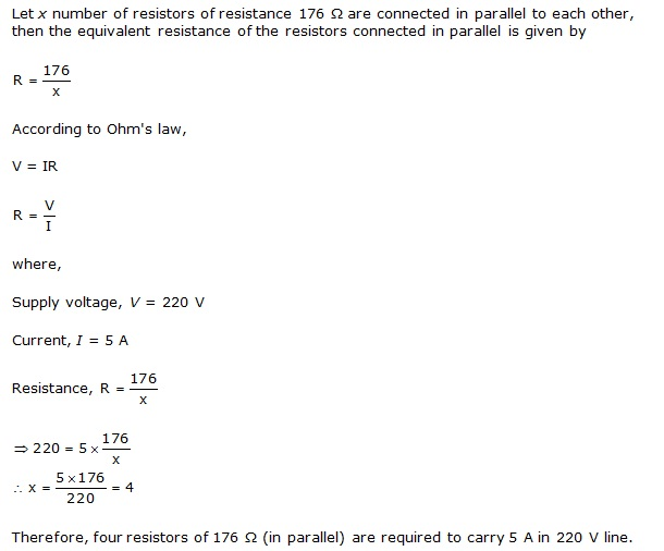
10. How many 176 Ω resistors (in parallel) are required to carry 5 A on a 220 V line?
Ans.
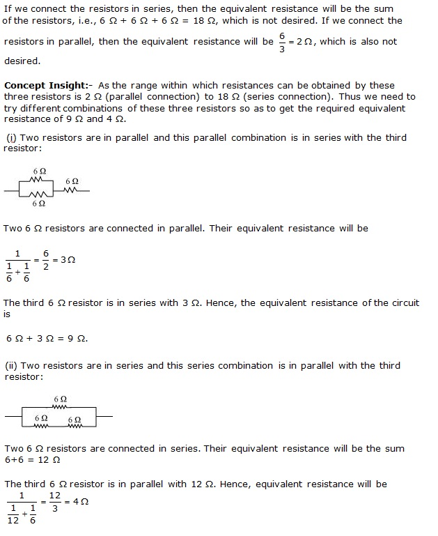
11. Show how you would connect three resistors, each of resistance 6 Ω, so that the combination has a resistance of (i) 9 Ω, (ii) 4 Ω.
Ans.
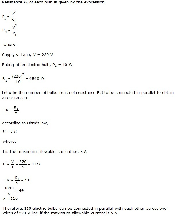
12. Several electric bulbs designed to be used on a 220 V electric supply line, are rated 10 W. How many lamps can be connected in parallel with each other across the two wires of 220 V line if the maximum allowable current is 5 A?
Ans.
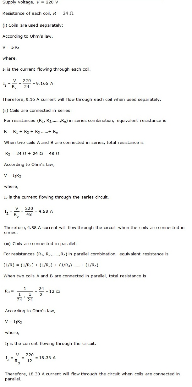
13. A hot plate of an electric oven connected to a 220 V line has two resistance coils A and B, each of 24 Ω resistances, which may be used separately, in series, or in parallel. What are the currents in the three cases?
Ans.
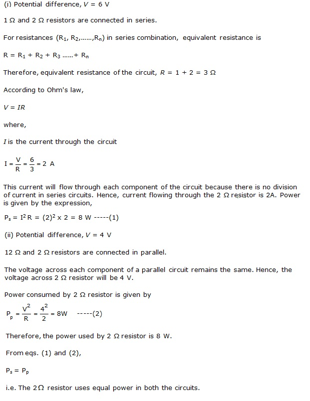
14. Compare the power used in the 2 Ω resistor in each of the following circuits:
(i) a 6 V battery in series with 1 Ω and 2 Ω resistors, and
(ii) a 4 V battery in parallel with 12 Ω and 2 Ω resistors.
Ans.
15. Two lamps, one rated 100 W at 220 V, and the other 60 W at 220 V, are connected in parallel to electric mains supply. What current is drawn from the line if the supply voltage is 220 V?
Ans. Both the bulbs are connected in parallel. Therefore, potential difference across each of them will be 220 V, because no division Of voltage occurs in a parallel circuit.
16. Which uses more energy, a 250 W TV set in 1 hr, or a 1200 W toaster in 10 minutes?
Ans. Rate of heat produced by a device is given by the expression for power as, P= I2R
Where,
Resistance of the electric heater, R= 8 Ω
Current drawn, I = 15 A
P= (15)2 x 8 = 1800 J/s
Therefore, heat is produced by the heater at the rate of 1800 J/s.
17. An electric heater of resistance 8 Ω draws 15 A from the service mains 2 hours. Calculate the rate at which heat is developed in the heater.
Ans. Rate of heat produced by a device is given by the expression for power as, P= I2R
Where,
Resistance of the electric heater, R= 8 Ω
Current drawn, I = 15 A
P= (15)2 x 8 = 1800 J/s
Therefore, heat is produced by the heater at the rate of 1800 J/s.
18. Explain the following.
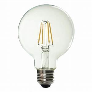
(a) Why is the tungsten used almost exclusively for filament of electric lamps?
(b) Why are the conductors of electric heating devices, such as bread-toasters and electric irons, made of an alloy rather than a pure metal?
(c) Why is the series arrangement not used for domestic circuits?
(d) How does the resistance of a wire vary with its area of cross-section?
(e) Why are copper and aluminium wires usually employed for electricity transmission?
Ans. (a)The melting point and resistivity of tungsten are very high. It does not burn readily at a high temperature. The electric lamps glow at very high temperatures. Hence, tungsten is mainly used as heating element of electric bulbs.
(b) The conductors of electric heating devices such as bread toasters and electric irons are made of alloy because resistivity of an alloy is more than that of metals. It produces a large amount of heat.
(c) There is voltage division in series circuits. Each component of a series circuit receives a small voltage for a large supply voltage. As a result, the amount of current decreases and the device becomes hot. Hence, series arrangement is not used in domestic circuits.
(d) Resistance (R) of a wire is inversely proportional to its area of cross-section (A), i.e.,
R ∝ 1A
(e) Copper and aluminum wires have low resistivity. They are good conductors of electricity. Hence, they are usually employed for electricity transmission.
Class 10 Science Chapter-wise Explanation